

Controller Area Network (CAN) is a robust communication protocol widely used in embedded systems, particularly in automotive, industrial, and automation applications. This example demonstrates how you can use Embedded Proto to structure data exchanges over a CAN bus. In this setup, Embedded Proto helps define messages for controlling a net booting process in the microcontroller, such as setting the microcontroller in flash update mode, erase flash sectors or write data into the flash. By using structured data, communication between devices via CAN becomes more efficient and reliable.
In the following, we will take you through the setup of this example, what kind of messages are used, and how the embedded code receives and sends the messages. Finally, we will look at how to run the code.
Source Code
The source code for this example is available on GitHub.Version
This example is up to date with version 3.4.1 of the source code.The setup
During this example, we are using a FRDM-KE06Z made by NXP. This is an easy-to-use development board with an ARM Cortex-M0+ processor. The board does not require an additional programmer and is readily available. The board includes the SN65HVD230 CAN transceiver. In order to communicate with the PC, a USB to CAN converter compatible with the socketcan interface is needed, for example the Canable Pro .
- Connect the FRDM-KE06Z can pins with the USB to CAN converter. It is good practice to twist the cables to reduce interference.
- CAN_H with CAN_H
- CAN_L with CAN_L
- GND with GND
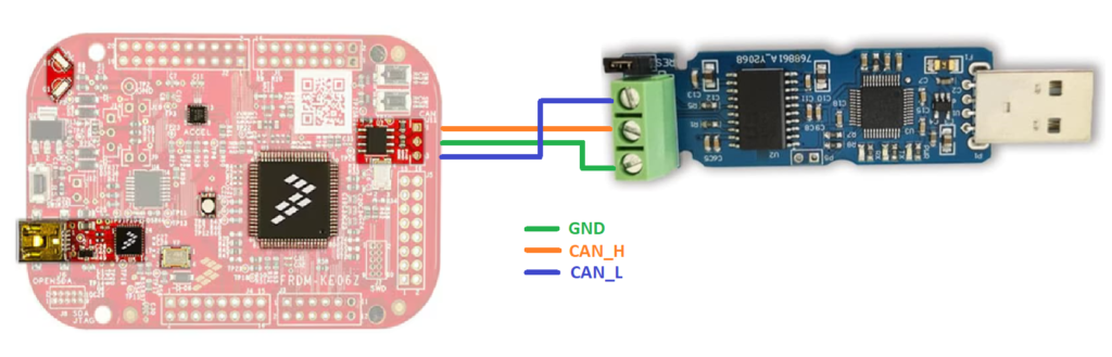
- Connect the development board via USB to your PC.
- Connect the USB to CAN converter to the PC.
The code in the repository is divided into four folders:
Tree -L 1
.
├── desktop
├── EmbeddedProto
├── frdm-ke06z
└── proto
The desktop folder holds the scripts to be run on the PC. It is a Python script used to make a CAN connection with the microcontroller and transmit and receive messages.
The EmbeddedProto folder holds Embedded Proto as a git submodule. This way, it is possible to track matching versions of this example and Embedded Proto.
The frdm-ke06z folder holds the embedded code. It is a project made with MCUExpresso version 11.10.0. The IDE generated most of the code to get a quick start on the basic initialization of the GPIO, CAN driver and FLASH driver. The proto folder holds the definition of the protocol buffer messages used in this example. The following paragraph discusses these messages in more detail.
Installation and Setup
The details on how to install this example are described in the README present in the repository with the source code.The messages
For this example, two messages have been defined. The first one is a command message and contains a mandatory field “action” to indicate which action should be executed. Also, it contains two optional fields “address” and “data” which are used when the microcontroller’s flash is manipulated. The microcontroller receives this command message and executes one of the following actions
- HookUp: puts the microcontroller in flash update mode
- Erase: Erase the flash sector indicated by the “address” field
- Write: Write the data indicated in the “data” field into the specified address
- Jump: Once the new binary is written, tell the microcontroller to jump into it.
- Quit: Cancel the process, the microcontroller will restart.
The second message is the reply and specifies the command action and if it succeeded or not.
enum Action
{
    Undefined = 0;
    HookUp = 1;
    Erase = 2;
    Write = 3;
    Read = 4;
    Jump = 5;
    Quit = 6;
}


message Data
{
    uint32 len = 1;
    bytes buf = 2 [(EmbeddedProto.options).maxLength = 256];
}

message Command
{
    Action action = 1;
    optional uint32 address = 2;
    optional Data data = 3;
}

message Reply
{
    enum Status
    {
        Undefined = 0;
        Succeed = 1;
        Failed = 2;
    }
    Action action = 1;
    Status status = 2;
    optional uint32 address = 3;
    optional Data data = 4;
}
Sending and receiving over CAN
Next, we will look at the embedded code and how the CAN communication works. The can frame is the following:
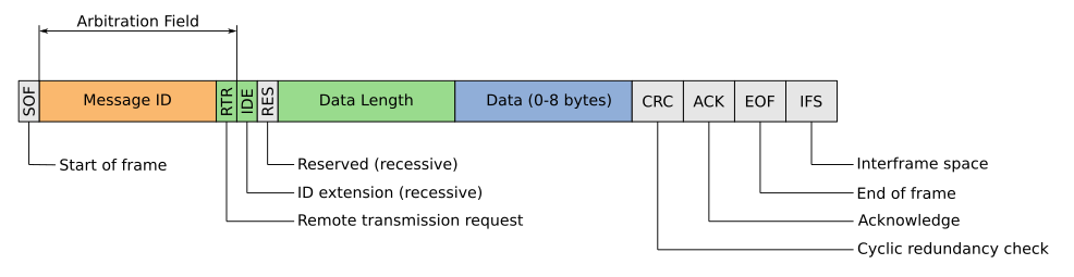
The Arbitration field contains the ID with which the board identifies itself on the CAN network. It is defined here for the FDRM-KE0z code and here for the Python script.
The “data length” and “data” fields are used to send a payload within the packet. This example uses classic CAN which allows sending up to 8 bytes per packet, so we must compose the messages by several CAN packets in order to send the content of a flash sector. This is done by using an empty packet (data length field equal to zero) as a flag to indicate the message has ended. The processing of the CAN messages are described in the CanBus.cpp file.
CAN data payload length
While in Classic CAN the data field length is 8 bytes, with the introduction of CAN FD (Flexible Data-rate), this limitation has been extended. In CAN FD, the data field can carry up to 64 bytes of data per message.Embedded data processing
Reception and deserialization of Command messages are done in the CanNetbooting::receiveCommand function. CanNetbooting class uses a ReadBufferFixedSize instance to hold the received bytes and to deserialize the message. Serialization and transmission of Reply messages are done in the CanNetbooting::sendReply function. CanNetbooting class uses a WriteBufferFixedSize instance to hold the serialized command.
Running the code
- Load the code into the FRDM-KE06Z using MCUExpresso
- Go to EmbeddedProto_Example_FRDM_CAN_Bootloader directory and activate the virtual env which has been created in the installation steps
cd EmbeddedProto_Example_FRDM_CAN_Bootloader
source desktop/venv/bin/activate
- Run the script. It will transfer an example binary which blinks the red LED. After the transfer is done the board will jump to this new firmware and the red LEd will start blinking.
python3 desktop/main.py desktop/assets/frdmke06z_led_blinky_RED.bin
In case the can interface is not up, the script will run “sudo ip link set can0 up type can…” in a subprocess, so the sudo password will be required The script console output will look like this,
CAN interface 'can0' is either down or set with a different bitrate.
Setting up the 'can0' interface with bitrate '1000000'
[sudo] password for ****:
CAN interface 'can0' set up successfully.
Hooking up...
Device hooked
Starting to flash desktop/assets/frdmke06z_led_blinky_RED.bin (7304 bytes)...
erasing 0x0x0
writting 0x0x0
...
erasing 0x0x1a00
writting 0x0x1a00
writting 0x0x1b00
erasing 0x0x1c00
writting 0x0x1c00
desktop/assets/frdmke06z_led_blinky_RED.bin Flashed
Jumping to the app...
Bootloader jumped!
And the FRDM-KE06z uart will look like this
(main) Opening CAN interface
(main) Opening Flash driver
(main) - Start address 0x10000
(main) - Sector size 512
(main) Netbooting state: WAITING_HOOK
(receiveCommand) Received 2 bytes
(receiveCommand) Received EOF
(sendReply) 4 bytes sent
(sendReply) EOF sent
(main) Netbooting state changed from 'WAITING_HOOK' to 'HOOKED'
(receiveCommand) Received 4 bytes
(receiveCommand) Received EOF
(hooked) Erasing 0x0
(sendReply) 4 bytes sent
(sendReply) EOF sent
(receiveCommand) Received 8 bytes
...
(receiveCommand) Received 5 bytes
(receiveCommand) Received EOF
(hooked) Writting 0x0
(sendReply) 4 bytes sent
(sendReply) EOF sent
....
(hooked) Erasing 0x1c00
(sendReply) 4 bytes sent
(sendReply) EOF sent
(receiveCommand) Received 8 bytes
...
(receiveCommand) Received 6 bytes
(receiveCommand) Received EOF
(hooked) Writting 0x1c00
(sendReply) 4 bytes sent
(sendReply) EOF sent
(receiveCommand) Received 2 bytes
(receiveCommand) Received EOF
(sendReply) 4 bytes sent
(sendReply) EOF sent
(main) Netbooting state changed from 'HOOKED' to 'JUMP'
(jump) Jumping to 0x10000 (0x10000)
The script allows you to change the CAN configurations such as bitrate, can interface name and remote device id. To know how to use the script run its help prompt
$ python3 desktop/main.py --help
usage: main.py [-h] [-i INTERFACE] [-b BITRATE] [-t TARGET_ID] binary

Set up CAN interface with a specific bitrate.

positional arguments:
  binary                Path to the firmware binary

optional arguments:
  -h, --help            show this help message and exit
  -i INTERFACE, --interface INTERFACE
                        CAN interface to use (default: can0)
  -b BITRATE, --bitrate BITRATE
                        Bitrate to set on the CAN interface (default: 1000000)
  -t TARGET_ID, --target-id TARGET_ID
                        Target device CAN ID (default: 2049)