

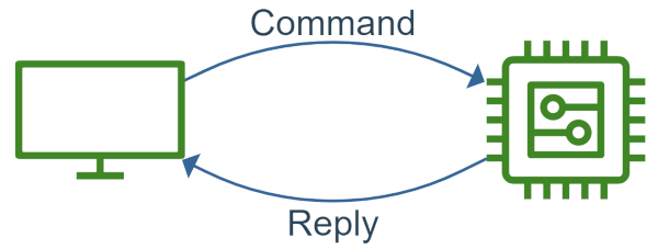
Connecting a microcontroller with a PC is straightforward when using google protocol buffers. This example shows you how you could communicate over UART in a structured manner. Embedded Proto generates the embedded code while regular protoc code is used for the python desktop script. Commands are sent from the PC to the microcontroller. The chip will reply with a message to give a status update.
We have selected a fairground game to have a simple goal for this example. Here we pretend that the PC controls a grappling hook to catch yourself a prize! The user gives commands to move the hook around. The controller will return the current position of the hook. When desired, the user can press the grab button to see if they win.
In the following, we will take you through the setup of this example, what kind of messages are used how the embedded code receives and sends the messages. Finally, we will look at how to play the game from your PC.
Source code
The source code for this example is available on GitHub.Version
This example is up to date with version 3.4.2 of the source code.The setup
During this example, we are using a NUCLEO-F446RE made by ST Microelectronics. This is an easy-to-use development board with an ARM Cortex-M4 processor. The board does not require an additional programmer and is readily available.
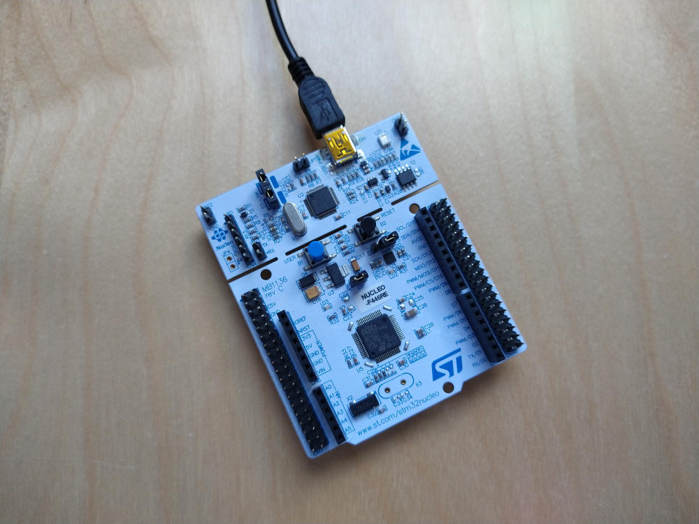
Just connect the board via USB to your PC to be able to program it. This same USB cable doubles as a virtual comport. Thus for this example, no additional converters or cables are required.
The code in the repository is divided into four folders:
tree -L 1
.
├── desktop
├── EmbeddedProto
├── nucleo-f446re
└── proto
The desktop folder holds the script to be run from the PC. It is a python script that uses the COM port to transmit and receive messages.
The EmbeddedProto folder holds Embedded Proto as a git submodule. This way, it is possible to track matching versions of this example and Embedded Proto.
The nucleo-f446re folder holds the embedded code. It is a project made with STM32CubeIDE version 1.3.0. Most of the code was generated by the IDE to get a quick start on the basic initialization of the GPIO on the board.
The proto folder holds the definition of the protocol buffer messages used in this example. The following paragraph discusses these messages in more detail.
The messages
Two messages are defined for this example. The first is the command going from the desktop computer to the microcontroller. The message defines an enumeration of all the different buttons that can be pressed in the console. The second variable sent along is a value stating the amount the desired motion should be.
message Command
{
  enum Buttons
  {
    DoNothing = 0;
    Up    = 1;
    Down  = 2;
    Right = 4;
    Left  = 3;
    Grab  = 5;
    Stop  = 6;
  }

  Buttons button = 1;
  uint32 value   = 2;
}
When the microcontroller receives a command, it will update its state. The new state will be sent back in a reply message. The position of the grappling hook is given by an x and y coordinate. A boolean indicates if you have won a price. Upon stopping the game, the position will be reset to zero.
message Reply
{
  optional int32 x_pos = 1;
  optional int32 y_pos = 2;
  bool price  = 3;
}
The x and y coordinates are marked as optional fields. The data of optional fields are always serialized even when they have the default value, zero in this case. On the desktop terminal, we will now also see the zero positions printed out. To learn more about optional fields please visit the documentation page.
Sending and receiving over UART
Next, we are going to take a look at the embedded code and how the communication flows over UART. This has been set up very simply in this basic example. Each message transmitted is preceded by one byte stating how long the serialized message is. This is done to know when a complete message has been received.
Stepping through the process, we start on the desktop. The user presses one of the command keys, triggering a Command message’s serialization. The serialized data is not directly transmitted, as stated above. First, the size of the serialized data is transmitted, followed by the data itself.
The embedded code will thus first read only one byte. Once received, that byte will be used to determine how many bytes will follow. The following embedded code illustrates this:
uint8_t n_bytes = 0;
receive_status = HAL_UART_Receive(&huart2, &n_bytes, 1, 100);
if(HAL_OK == receive_status)
{
  // Read the actual data to be deserialized.
  uint8_t byte;
  for(uint8_t i = 0; (i < n_bytes) && (HAL_OK == receive_status); ++i)
  {
    receive_status = HAL_UART_Receive(&huart2, &byte, 1, 100);
    read_buffer.push(byte);
  }
}
The read_buffer instance is used as a wrapper around an array of bytes. This class interfaces with a message object when deserializing the data. If no errors occur during transmission, we can safely use the message and process it.
auto deserialize_status = received_command.deserialize(read_buffer);
if(::EmbeddedProto::Error::NO_ERRORS == deserialize_status) {
  // Process the command.
  process_command(received_command, outgoing_reply);
}
In the processing function, a reply is formulated. Transmitting the reply uses the same method as the command. First, send the size followed by the serialized data.
// Serialize the data.
auto serialization_status = outgoing_reply.serialize(write_buffer);
if(::EmbeddedProto::Error::NO_ERRORS == serialization_status)
{
  // First transmit the number of bytes in the message.
  n_bytes = write_buffer.get_size();
  HAL_UART_Transmit(&huart2, &n_bytes, 1, 50);
  // Now transmit the actual data.
  HAL_UART_Transmit(&huart2, write_buffer.get_data(), write_buffer.get_size(), 50);
}
After transmitting the reply, the embedded code will start waiting for a new command.
Transmission schemes
The method of transmission by sending the size in one byte is very limited. It only allows messages with a maximum size of 255 bytes. Also this scheme performs no crc checks. More robust options are available for actual real life implementations.Running the game
Finally, we can try our luck and see if we can grab a stuffed animal. Program the NUCLEO, connect it to your desktop and run the script. The detail on how to install the example and run the code is described in the README file of the example.
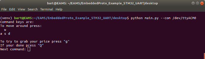
The command terminal code to start the desktop script in the python virtual environment is:
cd desktop
source venv/bin/activate
python3 main.py --com /dev/ttyACM0
In our case, the com port to which the NUCLEO was connected was ttyAMC0.
If you find this kind of example informative please consider reading one of our other examples like A simple Arduino IoT example with Protobuf.